
In this post Rifleshooter.com will build a clone of the United States Marine Corps M40A3 Sniper Rifle.
Replacing the M40A1 in 1999, and used by the Marines until 2009, the M40A3 is characterized by its heavy 25″ long barrel (24″ from the recoil lug), lug slotted optical platform and McMillan A4 stock. The M40A3 underwent a mid-life upgrade in 2007 when the D.D. Ross hinged floorplate system was replaced with a Badger M5 detachable magazine system. The rifle built here is based on this later, post-2007 version of the M40A3.
Unlike sniper rifles used by other services in the U. S. Military, the Marines build their own at the Precision Weapons Section (PWS) in Quantico, Virginia. The Marines who build these rifles have the military occupational specialty (MOS) of 2112, Precision Weapons Repairer/Technician (read more about the PWS and USMC 2112s here).
Prior to building a replica of a military rifle, you need to find the parts. This can be the most difficult step in the process. A complete list of parts needed to complete a USMC M40A3 (or A5) can be found in Rifleshooter.com’s previous post, USMC M40A5 Build- Part 1: Gathering the Parts. Note: Rifleshooter.com’s USMC M40A5 Build series, presents construction of an M40A5 in five different posts, most of which is common to the M40A3. I would suggest reading the series if you are considering building a M40A3 or M40A5 clone.
The M40A3 uses a lug slotted receiver to receive the optical platform (scope base). More information about the lug and clip slotted receivers used by the Marines can be found in Remington 700 (USMC M40A1, M40A3, M40A5) Q&A: What is a clip slot? Lug slot? Lugged base?
During an undertaking such as this, the desire to copy as much as possible from the issue rifle is desirable, however, I will take a few liberties:
- the McMillan A4 stock will have one knob to adjust the cheek piece- the originals had two, this two screw stock is no longer in production
- a Shilen 1:10 M40 contour barrel will be used in place of the Schneider 1:12- I would like the ability to shoot heavier bullets and have had great luck with Shilen barrels
- a Timney 510 trigger will be used instead of an M24 trigger- the Timney is great and the correct M24 triggers are pricey and hard to source
- metal will be coated in Cerakote rather than block oxide- Cerakote is a superior finish and I don’t have the equipment to black oxide the metal parts
A great reference for M40A3 and M40A5 information is TM 05539-IN, which is the Technical Manual for the M40A3 and M40A5. You can find a copy of it here. TM 05539-IN is a length document that covers a wide variety of topics directly relating to both rifles.
The contents of Rifleshooter.com are produced for informational purposes only and should be performed by competent gunsmiths only. Rifleshooter.com and its authors, do not assume any responsibility, directly or indirectly for the safety of the readers attempting to follow any instructions or perform any of the tasks shown, or the use or misuse of any information contained herein, on this website.
Any modifications made to a firearm should be made by a licensed gunsmith. Failure to do so may void warranties and result in an unsafe firearm and may cause injury or death.
Modifications to a firearm may result in personal injury or death, cause the firearm to not function properly, or malfunction, and cause the firearm to become unsafe.
For use in this project, the following items were ordered from Brownells:
- Shilen 30 caliber #7 select match barrel blank
- Badger M5 bottom metal
- Calipers
- Manson Receiver Accurizing kit
- Manson receiver ring facing tool
- Brownells bolt lapping tool
- Manson bolt face truing block and burr
- 3/8″ 35-degree profile tool
- 1/2″ High-speed steel threading tool
- Manson 308 Match reamer
- Marine-Tex epoxy
All lathe work is conducted on a Grizzly gunsmith’s lathe.
Parts in hand, I am ready to start working on the rifle. I’ll start by machining the receiver. First, I’ll cut the lug slot to install the optical mounting platform, then, I’ll blueprint the action and lap the bolt lugs.


The optical platform used in the M40A3 is shown above. Note the two lugs that protrude beneath the base. These lugs provide added strength to the mount.

Over the years I’ve searched and I still can’t find a set of drawings for lug slotting a mount. Talking to Dan Ross (D.D. Ross) who designed the mount for the Marines, and Dave Clark (CHPWS), the former Staff Non-Commissioned Officer-in-Charge (SNCOIC) of the Precision Weapons Section at Quantico, they both suggested measuring the mount and cutting it to fit. I took their advice and made the drawing of the mount above. A quick note: I’ve lug slotted two receivers prior to this, so, I am still in the process of fine tuning the process, measurements and drawings.

The action is secured to a v-block and secured in the milling machine vise. After the action is centered, and the location of the 2nd screw hole is determined, initial cuts are made with a 7/16″ 4 flute high-speed steel end mill. The first cut plunges into the front of the receiver, this will accept the front lug of the mount. Note: the second screw hole from the front of the receiver is considered the datum for all cuts I’ll be making. The 7/16″ end mill is also used to open up the rear of the lug mount.

Switching to a 1/8″ solid carbide end mill, the rear of the lug cut if squared off. A Digital Readout (DRO) makes this a fairly simple process, the numbers I used for this mount are shown in the shop drawing above.

A quick test fit shows the front and rear lugs of the optical mounting platform both fit. Note the mount still does not sit flush on the receiver.

A 9/64″ solid carbide end mill is used to open up the screw holes. A solid carbide end mill is used because it does not deflect like a drill bit. This is important if the factory holes are misaligned.

An 8-40 tap is used to finish the holes. The tap is guided by a spring loaded tap guide in the mill. This ensures the tap is perpendicular to the hole.

Switching back to the 7/16″ end mill, the rear shelf of the receiver is cut flat, .135″ lower than the front of the receiver.

A quick check shows the mount sits flush.

The final step is to open up the ejection port. For this I use a 7/16″ ball end mill. I take a series of light passes, .008-.010″ at a time.

When the action comes off the mill, I clean it and install the optical mounting platform. It is important to make sure everything is properly aligned and fits well. Looks good, time to blueprint the action.

Like the Marine Corps PWS, I like to use the Manson Receiver Accessorizing System shown above. The kit consists of a two reamers, two tapered bushings and a .010″ over-sized receiver tap.

The action is held in a Brownells action wrench. The two tapered bushings from the Manson kit are inserted into the bolt raceways. These bushing guide the reamer and tap.

A front view of the receiver as provided by the factory.

The reamer is used to cut the minor diameter of the threads as well as the receiver lugs.

The action after the receiver reamer makes its cuts.

The receiver tap follows the reamer.

The tap serves as a guide for the receiver ring facing tool. This tools has three carbide cutters and trues the front of the receiver.

Note the trued front of the receiver ring.
Before working on the bolt I check its fit against the receiver lugs. Occasionally, a factory Remington 700 action will only have one bolt lug engaging the receiver lugs. To check this, I put marker on the receiver lugs, insert the bolt, and work the handle while applying rearward pressure to the bolt. If the marker is removed from both lugs, the bolt is contacting them. In cases when the bolt only contacts one lug, I’ll mount the bolt in a lathe and trim a few thousandths off the rear of the lugs to even them up. On this action, both lugs contacted the receiver lugs, so I’ll move straight to lapping the lugs.

To lap the bolt lugs I’ll be using 600 grit abrasive and a Brownells lapping tool (above).

Lapping compound is applied to the front surfaces of the receiver lugs. The lapping tool screws into the front of the receiver, it provides rearward pressure on the bolt. As the bolt handle is lifted up and down, the mating surfaces are lapped together.

Note the contact surfaces of the bolt lugs after the lapping process.

The bolt face will be cut with a Manson tooling block and bolt face burr. This operation can also be performed on a lathe, however, this method is faster.

A view of the bolt face from the factory (above).

The receiver is secured in an action wrench and the tooling block attached to the front of receiver. Oil is applied to the bolt face and a drill is used to power the carbide burr, cutting the bolt face.

After a few minutes of work, the bolt face is now perpendicular to the action.

A view of the trued, or “blueprinted” receiver. For cosmetic reasons, on some rifles, I trim the front of the bolt nose and recoil lugs, on this rifle, built for hard field use, I didn’t feel it was necessary.

The receiver is secured in a vise with the bolt in place. A depth micrometer is used to measure the distance from the front of receiver; to the bolt face (A), to the front of the bolt lugs (B) and to the bolt nose (C). These dimensions, with the thickness of the recoil lug, are used to calculate the final size of the barrel tenon and determine its head space measurement.

This rifle will be equipped with a Shilen Select match barrel. Barrel makers mark the chamber end of barrel blanks with the barrel’s specifications. In this case (above, from the top, clockwise), “Shilen” is the manufacturer, “308” the caliber, “7” the profile, “10” the twist rate, and “SM” for select match.

Prior to fitting the barrel I place it in the stock to make sure it will fit. This helps me determine how much of the shank to remove. On the Schneider barrel blanks, the Marines remove approximately .250″ before chambering. Since I am using a Shilen, I’ll remove one inch from the chamber end as directed by the manufacturer.

The barrel is mounted through the head stock of the lathe. The chamber end is secured in a spider plate, which has four screws for centering the bore.

The muzzle passes through the rear of the headstock where it is centered by a second spider.

The barrel is now dialed in so the bore is concentric to the lathe. There a few different ways to do this. In this case, I am using a precision ground range rod and a dial indicator. After the chamber end is dialed in, the muzzle end of the barrel is dialed in as well. This is repeated until both ends of the barrel run are dialed in. Some gunsmiths prefer to only dial in the chamber end; I used to do this, but prefer this method now.

The end of the barrel is cut square and a tenon is cut to allow the recoil lug to slide into place. The lug should fit firmly against the shoulder of the barrel and sit snug against the tenon. I’ve been making this cut with a high-speed steel 35-degree profile tool from Brownells. This tool allows you to cut a square shoulder against the tenon. The spindle speed is 360 RPM.

The tenon is coated in Dykem in preparation for threading. A stop groove is cut where the recoil lug ends and the threads begin.

Note the relationship of the recoil lug and the stop groove. This allows the action to be tightened against the lug once the threads are cut.

Threads are cut with a high-speed steel insert cutter. I thread at 220 RPM and use Do-Drill high sulfur cutting oil as a lubricant. This is the first pass to ensure set up is correct.

I cut a few thousandths and continually try to test fit the action. Once the action fits, I test fit it with the recoil lug.

The finished threads look pretty clean. I’ve been changing back and forth between the high-speed steel and carbide inserts for cutting barrel tenons and I think with my lathe and the speeds I use, the high-speed steel is a little easier to work with.

The M40A3, like all Remington 700 rifles, requires a bolt nose recess in the chamber end of the tenon. This can either be cut with a boring bar, or a form tool like this piloted counter bore. I find the counter bore easier to use. The tool is held with a pair of pliers, and the depth of cut is determined by the dial indicator reading off of the spring clamp on the quill. This one is .705″ in diameter, providing .0025″ of clearance around a factory bolt.

The counter bore does a great job cutting the bolt nose recess.

Time for another test fit. This time to ensure the action, lug and bolt all fit.

The chamber will be cut with a live pilot Manson 308 Match reamer. Live pilots are available in .0002″ increments, I always try to select a pilot that has a light drag in the bore. The stop collar on the reamer is a PTG adjustable reamer stop. It is initially adjusted against a head space gauge to cut the chamber short.

The shank of the reamer is held with a small pair of locking pliers. The pliers rest against the lathe’s cross slide. A dead center in the tail stock drives the reamer into the chamber. I’ve cut chambers a number of different ways, and I’ve held reamers is almost every imaginable fashion, this is my preferred set up.
 This barrel was chambered with a spindle speed of 70 RPM. The reamer was coated in Do-Drill cutting oil, gently fed into the cut. The reamer was cleaned and lubricated frequently.

When the reamer stop contacts the barrel, it is time to check head space.

The action and lug are screwed onto the barrel with a go gauge in the chamber. A feeler gauge is used to determine the space between the action and the lug. This dimension is how much deeper the chamber needs to be cut. The reamer stop is dialed back half of this distance and the process repeated until the action and lug are tight on the barrel tenon and the bolt handle closes on the go gauge.

When the chamber is the correct depth of cut, the bolt handle should close on the go gauge, and stay open on the no go gauge (above). Keep in mind when the barrel is torqued on, it will most likely crush another .001-.002″ of an inch.

A view of the finished chamber cut. Note the sharp edge of the bolt nose recess and the chamber.

The edge of the chamber is broken and a radius is cut on the edge of the bolt nose recess. The radius on the chamber prevents brass from scratching and aids in feeding. The radius on the bolt nose recess helps the cartridges feed.

To cut the crown the barrel is reversed in the head stock of the lathe and dialed in.

The M40A3 crown has a 45 degree pull back (all source agree on this). Depending on source, it is either .080″ or .090″ deep (I’ve had USMC PWS 2112s tell me both). According to Dave Clark, former SNCOIC of the USMC PWS, and co-owner of C&H Precision Weapons Shop , the cut is made by making a series of plunges with a boring bar. He suggested zeroing the DRO, plunging in .020″ and coming out to .375″, then repeating these cuts in .020″ increments at .360″, .345″ and .330″. Once the final cut is made, he suggested retracting the boring bar with the compound set at 45 degrees to make the pull back cut. Since Dave knows way more than I do, I tried his method. The picture above shows the series of plunge cuts.

A top view of the set up. Note the compound is set to 45 degrees.

The crown looks great.

I like to break the edge of my crowns with a piloted counterbore. I use both 45 and 60 degree counter bores for this. On this rifle, I am using a 60 degree counterbore. This method is not used by the Marines, however, I did it to remove any potential burrs.

The barrel is mounted in a barrel spinner and ground with 320 grit abrasive cloth on a belt sander prior to installation. Gary Schneider, maker of the spec barrel used on the M40A3 and M40A5 ships his barrels with the tooling marks in them. For a period of time the PWS left the marks to hold spray paint better when the rifles in the field. Dave Clarke, former SNCOIC of the PWS, changed this practice and started polishing the barrels when he ran the shop- so both approaches to the barrel finish are correct.

A small amount of anti-seize is placed on the threads to prevent the action and threads from binding together. A lug alignment tool is attached to the bottom of the action. This ensure the lug remained perpendicular to the action when it is tightened.

A Farrell barrel vise holds the barrel in place. A Surgeon port entry action wrench, attached to a torque wrench is used to tighten the barrel. I’ve used different torque specs over the years, currently, I am tightening my barrel to 75 ft/pounds. Once installed, I verify head space by ensuring the bolt closes on the go gauge and doesn’t close on the no go gauge.
A great reference for is TM 05539-IN, which is the Technical Manual for the M40A3 and M40A5. You can find a copy of it here. TM 05539-IN covers the bedding process used by the Marines in depth. As a matter of personal preference, I don’t like to bed bottom metal or use a barrel pad on rifles I build, so I’ll bed this rifle differently than the Marine Corps.

The barreled action can now be prepared for bedding. Metal surfaces are degreased (so tape will stick) and the front and sides of the recoil lug are coated in tape. Acra-Release is used to coat all metal surfaces and voids are packed with modeling clay. Acra-Release is reapplied to all surfaces.

During the bedding process the two aluminum pillars provided with the Badger M5 bottom metal need to be installed. These will be coated in epoxy and pushed up through the bottom of the stock. The mating surfaces of the stock are degreased and the a clay “snake” is placed in front of the recoil lug slot to prevent epoxy from moving forward.

The pillars are installed.

mating surfaces are coated in Marine-tex epoxy.

The action is placed in the stock, bottom metal installed, and the action screws gently tightened. The excess epoxy is removed with cotton swabs and razor blades before it hardens.

Note the excess is epoxy is cleaned off. While I had the Marine-tex mixed, I took time to bed the optical platform. Dan Ross, former USMC 2112 and current owner of D.D. Ross suggested this step. He said the PWS did this with steel bed epoxy on the first M40A3s. The epoxy is allowed to cure for a day.

The excess bedding compound will squeeze into areas of the stock it shouldn’t be. To clean this up, the stock is placed in the mill and the excess is removed.

Many of the parts Marine Corps PWS rifles have their serial number marked. On the M40A3 and A5, the bolt handle, recoil lug, stock, bottom metal and optical platform all have the serial number marked on them. 
To prepare the parts for finish, they are hung outside on a rack. Brownells TCE spray degreaser is used to remove any oil from the surfaces.

The parts are moved to the blast cabinet where aluminum oxide abrasive is used to prepare the metal surfaces.
 Parts are degreased a second time and cleaned with compressed air. A tack cloth is used to wipe surfaces to ensure any aluminum oxide residue is removed.

Cerakote is applied with an HVLP sprayer. This is a IWATA I bought from Brownells. It works great.
 The parts are allowed to off gas for a while then cured in an oven. This one is designed specifically for firearms, you can read more about it here.

The last step is to put everything together. A Timney 510 trigger will be used instead of a Remington M24 trigger (the correct OEM part).


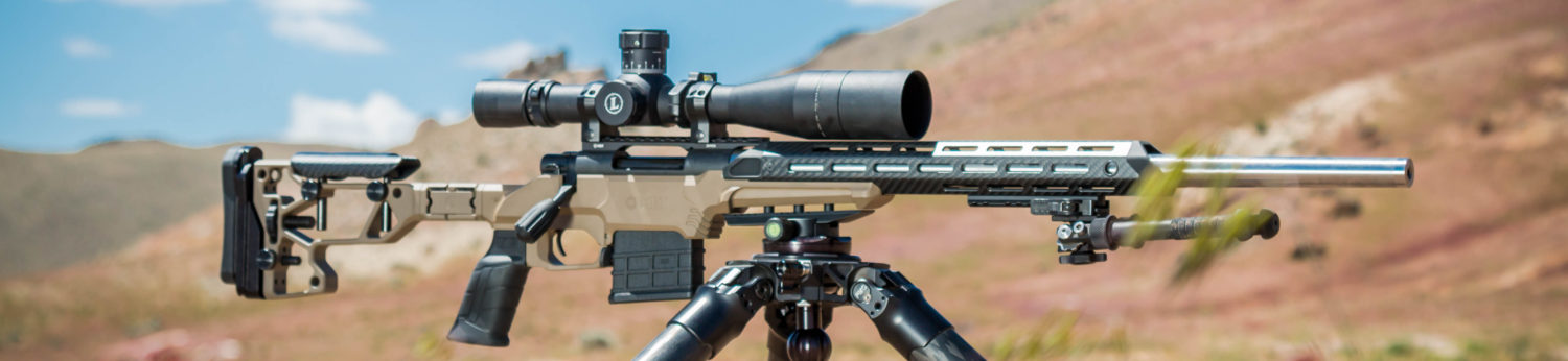
Looks great and it is ready for the range.


I don’t have the correct USMC issue scope, so I mounted a Leupold 3-18 Mark 6 scope in a Spuhr mount. I loaded up some 175 grain Sierra MatchKings over new Lapua brass, Wolf Primers and Varget. I fired one round at 50 yards to zero, and 7, 5 shot groups (36 rounds total) at 100 yards to get an idea how the rifle performs.

All groups were shot from a bipod with rear bag. Average 5-shot group size was .723″ (.690 MOA). I think with proper load development this will improve.

This was the best 5-shot group, .571″ (.545 MOA).

On the second trip to the range I swapped the Leupold for a NightForce F1 3-15. With the 175 SMKs, Varget and IMR 4064, thing were definitely getting better.

175 SMK 5-shots, prone, from a bipod with Varget .352″ (.336 MOA)!

175 SMK 5-shots, prone from a bipod, IMR 4064 .368″ (.351 MOA)!

Factory ammunition shoots well (above). This is 5-shots of factory Federal Gold Medal fired prone with a rear bag at 100 yards, .581″ (.555 MOA).
Looks like the rifle is a keeper. I’ll post more once I refine the load development process.
This post, as well as Rifleshooter.com’s M40A5 series, wouldn’t have been possible without the help of a number of people. I would like to thank the following individuals for their time, knowledge and assistance:
Dave Clark, former SNCOIC of the USMC PWS, and co-owner of C&H Precision Weapons Shop.
Dan Ross, former USMC 2112, owner of DD Ross and inventor of the optical platform used on the M40A3 and M40A5.
Gary Schneider, maker of the OEM barrels found on the M40A3 and M40A5.
Roy Hill, Brownells.
Sean Murphy, Nightforce Optics.
Dave Manson, Manson Precision Reamers, maker of the best reamers and receiver accurzing system.
If you liked this post, subscribe for free email updates on the top right side of the page!


You must be logged in to post a comment.