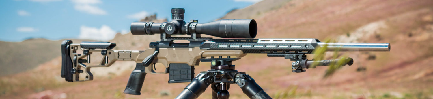
Our rifle in its current configuration. We added a SIRS mount, coated the metal in black Cerakote, the stock in olive drab and added a Surefire brake.
Custom Remington 700 Build: Our twist on a light tactical rifle
A blueprinted Remington 700 with a 20″ Shilen #6 barrel chambered in 308 Winchester in a McMillian A3 stock.Our rifle in its current configuration. We added a SIRS mount, coated the metal in black Cerakote, the stock in olive drab and added a Surefire brake.
Custom Remington 700 Build: We were looking to build a compact 20″ 308 capable of sustained sub-minute of an angle performance. This is an overview of our project.
This article is presented for information purposes only and provides an overview of the process we used and should not be construed as instructional advice. If you would like to learn more about chambering, the Viper bench-rest.com video on chambering a Remington action is highly recommended to learn more about the process.
Brownells provided the following tools, parts and accessories for this project:
The floating die holder was purchased from NeilsNiche.com.
New Remington 700 short action with a .308 bolt face.Remington 700 action and the Remington 700 Armorer’s kit. The armorer’s kit contains everything we need to assemble and disassemble our Remington 700.We use the bolt disassembly tool to grab and retract the firing pinOnce the firing pin is retracted, the firing pin assembly can be retractedThe ejector tool tool is used to remove the ejector from the bolt.
The “claws” of the ejector tool slide over the bolt lugs. The tool is then turned clockwise, engaging the ejector.
Using a pin punch and bench block, we remove the ejector pin. We remove the tool and slide the ejector and ejector spring out of the bolt.
Note the location of both trigger pins. The front pin cannot be removed with the factory bolt stop in place. The bolt stop, located on the other side of the trigger assembly blocks its removal.
The rear trigger pin is removed.
With the rear trigger pin removed, the bolt stop and bolt stop spring can be removed from the rifle as well as the sear spring from the trigger assembly.With the receiver disassembled, we secure all small parts in plastic bags to prevent loss.
We will use a receiver accurizing kit to true the minor diameter of the threads, square the receiver lugs and chase the threads.
TThe receiver accurizing kit contains two tapered bushings (top), a receiver tap/mandrel (middle) and a receiver reamer (bottom).
The kit includes two tapered bushings to guide the receiver reamer and tap. We tap our bushings into place.
The reamer is guided by the bushings into the receiver. Do-Drill cutting oil is used to provide lubrication. We check the receiver lugs after a few turns to verify the tool is cutting. When the lugs are clean, we remove the tool and clean the area.
This is the best picture we managed to get of the interior of the action after we cut the receiver lug face. When we started the bearing surfaces were blued from the factory, now they are shiny and square.
Next, we use the bushings to guide the receiver tap. This chases the threads and ensures they are square.
The receiver tap doubles as a mandrel to square the front face of the receiver on the lathe. Mounting one end in the chuck and contacting the other with your live center would allow the lathe operator to true the front face. We elected to go a different route.
The receiver ring facing tool is another option to square the face of the receiver if you don’t have access to or don’t want to use a lathe. The bushing on the tool is guided by the end of receiver tap.
When in use, the receiver ring facing tool is aligned on the receiver tap as shown.
Using the receiver facing tool, the front of the receiver is trued. The tool is placed over the tap and turned by hand. Here, you can see our progress after a few turns of the tool. We used Do Drill to lubricate it.
After a few more turns, the front of the receiver is now square.
Next, we will lap the lugs of our Remington 700 using the bolt lapping tool. The tool screws into the front of the action and applies rearward pressure on the bolt face. The lugs, now contacting the newly square receiver lug surfaces, can be lapped into place.
600 grit silicone carbide lapping compound is used to lap the bolt lugs.
A little bit of lapping compound is placed on the front of the receiver lugs. The bolt handle is then raised and lowered repeatedly. We periodically check our work. Note; it is critical that we do not get any lapping compound on any other surfaces.
Notice the shiny surfaces that have been trued. Once we have about 95% contact, we are finished. We then rinse all areas with TCE to remove any remaining abrasive.
The bolt face truing tool consists of a carbide cutter (bottom) and a tooling block (top).
The tooling block is screwed into the receiver. The carbide cutting tool is then snapped underneath the extractor with a little bit of Do-Drill. The action is held horizontally in a padded vise. The bolt is inserted into the rear and the tool is pushed through the hole in the tooling block.
We attach a drill and run it at low rpm for a couple of seconds. The drill is removed and the bolt cutting tool retracted. If too much material is removed, firing pin protrusion can be an issue. We make sure to check our firing pin protrusion to make sure its safe and meets standards.
Here is our bolt face after a few seconds of cutting. Notice the outside edge of the bolt face is shiny, indicating the center of the bolt face was low. We will cut some more.
Our bolt face is now completely square to the action.
Our action is now blueprinted and ready for a barrel.
The blueprinted action is secured in the Holland sine bar and lug fixture (left). The lug, is secured to the action with the plug (bottom right).The bottom of the lug is aligned with the machined surface to ensure the lug is in the proper orientation prior to drilling.The entire fixture is secured in the mill’s vise and the supplied cobalt drill is used to drill the hole to the proper depth.Once the hole is drilled, we remove the lug and deburr the hole in the receiver, then reattach the lug and drive the supplied pin home.Prior to working on our barrel, we use a depth micrometer to carefully measure the distance from the front of the receiver to the bolt face, bolt nose and bolt lugs. This information will be used with our barrel tenon worksheet.This barrel chambering worksheet developed by Brownells, provides an excellent framework for calculating the dimensions of the tenon as well as the bolt nose recess depth.Barrel makers mark relevant information on the chamber end of the barrel blank. In this case “Shilen” is the manufacturer, “308″ is the bore diameter, “6″ is the contour, “S”denotes stainless steel and “10″ is the rate of twist (1:10).Shilen recommends cutting off 1″ from each end of the blank. We saved the ends for future reference.
This fixture is secured in the four jaw chuck. The set of screws on each end of the fixture are used to align the axis of the bore. The PTG “Grizzly” rod, front, is used to indicate the bore. The bushings at the end are interchangeable to securely fit.
The “Grizzly” rod (top) accepts different bushings (center) available in .0002″ increments. Shown here are bushings from .2992″ to .3008″. The bushings are secured to the rod via a set screw.
A dial indicator is used, in conjunction with fixture’s screws, to align the bore with minimum run out. We labeled the sides of our fixture so we could keep track of the opposite sides when performing this task.
With the bore dialed in, we make a cut across the rear face of the barrel to ensure that it is perpendicular to the bore, then we begin to cut the tenon to length. We used high-speed steel (HSS) insert tooling from Brownells and Viper’s Venom cutting oil. The combination of HSS tool and oil provides a smooth finish on stainless steel. The tenon will be initially cut to the diameter of the recoil lug.
These are the high-speed steel cutting tools used. The 1/2″ threader (left) is used for threading the tenon. The 35 degree profile bit (center left) is used to cut the recess in the tenon shoulder so the recoil lug will fit flush against it. The right hand cutting tool (center right) is used to cut the majority of the tenon and face the breech end of the barrel and the last bit (right)is used to cut the groove between the threads and cut shoulder that supports the lug and chamfer the end of the tenon prior to threading. Note the slight radius at the end of each cutter.
The insert tooling has a slight radius. Once the tenon is cut to diameter, the radius prevents the lug from firmly seating against the shoulder. Note the slight space in between the barrel shoulder and recoil lug shown here.
By plunging the cutter in slightly, the lug is now able to fit securely against the shoulder.
Once the tenon is the correct diameter for the recoil lug, a groove is cut between the threads and the area the tenon will rest on. This begins .005″ less the thickness of the lug from the shoulder. Layout fluid is applied to the tenon to aid in the process.
An indexable HSS threading tool from Brownells is secured in the tool holder. The compound is set at 29.5 degrees for threading operations and the center gauge is used to ensure that the threading tool is properly aligned.
After a light pass is made, a pitch gauge is used to verify that the lathe was set up properly. We take multiple light passes with our threading tool, advancing the compound slowly for a quality cut.
With the threads cut, anti seize is applied to the threads and then the recoil lug and action are test fitted to check our work.
This counter bore tool will be used to cut the bolt nose recess. We calculated the depth of cut earlier on the worksheet. The tool is secured in a floating reamer holder and guided by a pilot.
The counter bore is thoroughly lubricated with Viper’s Venom oil and cuts are taken .025″ at a time. We stop the lathe, retract the cutter, clean, lubricate and advance it to within a few thousandths, start the lathe and repeat the process.
To measure the depth of cut, we attached a spring clamp to our tail stock and used a dial indicator in a magnetic base.
Here is the finished bolt nose recess cut.
To ream the chamber, we secure our reamer in a floating reamer holder. The PTG MARS, or Micro Adjustable Reamer Stop, is secured to the reamer’s shank. This tool provides a means to accurately adjust the depth of cut.
Initially, we adjust the depth of cut short of our “go” gauge.
This is our reaming set up. The tail stock is tightened with a torque wrench to ensure consistent alignment. The floating reamer holder is lubricated. The chamber reamer is thoroughly coated in Viper’s Venom oil. We advance the reamer .025″ and make our cut after which we stop the lathe, retract, clean and lubricate the reamer. The reamer is advanced to within a few thousandths of the cut, lathe started and the process repeated.
When the MARS hits the rear face of the barrel the reamer is removed and cleaned.
Anti seize is applied to the barrel threads. The action and lug are threaded into place with the “go” gauge in the chamber. Once the action is tight against the gauge, feeler gauges are used to see how much deeper the chamber needs to be cut. The reamer stop is then adjusted to half of this depth and process repeated until the “go” gauge fits. When the “go” gauge fits, a “no-go” gauge is then used to verify the chamber hasn’t been cut too deep.
Here the “no-go” gauge is inserted into the chamber. Notice that the bolt handle does not close. At this point the chambering process is complete.
We decided on a 20″ barrel. Keep in mind, you can’t cut them any longer.
The barrel is secured in bronze vise jaws and cut on the waste side of the mark. Do Drill lubricates the saw.
A large file is used to remove the saw marks.
To crown the barrel we will use a Manson kit. We secure the appropriate arbor in the bore and start with the flat, zero degree cutter.
The cutter is lubricated with Do Drill oil.
With the crown flat, the 11 degree cutter is used.
Finally, a outside corner is eased with the tool.The finished 11 degree target crown.The barrel is secured in the barrel polishing fixture, The fixture, made of aluminum, has two nylon centers on each end that hold the barrel without damaging it.
The barrel is secured in the polishing fixture and the 6″ hard felt wheel is treated with Polish-O-Ray. A gloved hand is used to slow the rotation of the barrel as it is polished.
Since the barrel will eventually be blasted with aluminum oxide media and coated with Cerakote, it is only polished at 140 grit. The polished barrel (right), is compared to the factory finish (left).
The chambering, in this case .308 Win, is stamped onto the 9 o’clock position of the barrel. The stamping guide provides a precise way to align the stamps during this process.Use cheap stamps, get cheap results. We bought these imports on sale. We should have known better. The barrel is now ready for installation.Once the barrel has been cut and crowned, it is secured in a barrel vise and then an action wrench is used to torque the barrel into place. Headspace is checked and rechecked. The Barreled action is now complete.We decided to mount a tactical bolt knob on our rifle.We secured our bolt handle in the PTG fixture mounted in our lathe. The handle is carefully aligned. A #2 center drill is used to drill a hole for the tail stock.
The tailstock it used to help secure the handle. The knob is removed and tenon turned to the major diameter of the thread. Cuts are made from left to right, towards the tailstock.
Thread are cut to on the tenon. The bolt handle can now be installed.Our tactical bolt handle is ready to go.We are putting a McMillian A3 stock on our rifle. The stock comes with a barrel channel for a Remington factory varmint contour. Since our #6 contour is larger, we will have to open it up. We start by marking the outside edges with the action in the stock. A foredom rotary tool with a burr is used to make the rough cuts.Sandpaper is used to adjust the fit. We worked until we had an even .050″ clearance around the barrel.
We installed a Jewel trigger, dropped the action into the stock and torqued both screws. A Leupold Mark 4 4.5-14 X 50 scope was attached on a badger base and rings. A Harris BR bi-pod was attached to the stock.The results look good so far. After a quick bore sight, the bottom 5 round group was fired with Federal 168 Gold Medal at 100 yards. That flier is the first round out of the gun. This was our largest group of the day and measured .940″.
The rifle shot and handled well. On our first outing we fired four, five-shot groups measuring .940″, .653″, .767″, and .758″ from a bi-pod, on asphalt (no mats, we are studs), with a rear bag. We plan on adding pillars and skim bedding the stock and painting it. The rifle will be coated in Cerakote.
Our custom Remington 700 on the firing line.Five rounds at 500 yards. We still need to establish a zero. Federal 168 Gold Medal- 5.747″
Since its approval by SAMMI in 2011, the 300 AAC Blackout (abbreviated 300 BLK) has been a popular choice with shooters. Often recognized as the go to choice for suppressed applications with heavy subsonic loads; […]
The Glock has become a staple of the American shooting culture. Thirty years ago it would be hard to believe this boxy plastic and steel gun chambered in a puny cartridge would become as popular […]
7mm Remington Magnum load development: 197 gr and 183 gr Sierra MatchKings (SMK) In the days before the current 6.5mm craze, cartridges with a “metric” bullet size in the name never really caught on in […]


You must be logged in to post a comment.