
Custom 1911 Project: Part 4- Machining a chain link front strap, presented by Rifleshooter.com and Brownells
This is the fourth installment of our Custom 1911 project- in this post we are going machine a chain link pattern into the front strap of the pistol.
- Custom 1911 Project: Part 1- getting started
- Custom 1911 Project: Part 2-undercut trigger guard
- Custom 1911 Project: Part 3- fit and blend grip safety
- Custom 1911 Project: Part 4- Machining a chain link front strap
- Custom 1911 Project: Part 5- milling the slide for low mount sights
- Custom 1911 Project: Part 6- flat top and chain link top of slide
- Custom 1911 Project: Part 7- machining ball cuts on a 1911 slide

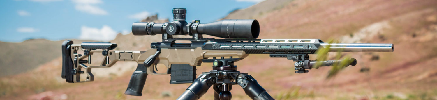
Our custom Remington R1 is outfitted with the following Wilson Combat parts:
- #298 BBP Bulletproof grip safety
- #463T Combat Pyramid sights
- #92 FS Smooth main spring housing
- #337 BC Bulletproof hammer
- #315B Pin set
- #316G Complete spring kit
- #314 Sear
- #573 Bulletproof disconnector
- #190M Medium trigger

In its original form the 1911 pistol had a smooth front strap on its frame. Over the 1911’s 105 plus years, gunsmiths have developed a series of modifications to texture this surface to allow the shooter a more positive gripping service. Some are checkered, some are machined with patterns and some are simply textured; they all enhance grip-ability. Beyond improving the handling characteristics of the pistol, most of these custom touches also enhance the look of the firearm. Checkering, stippling and matte textures can be cut with hand tools. Some of the newer, repeating patterns like chain link and snake skin need to be cut on a machine. In this post, we will machine a chain link pattern onto the front strap of a 1911. The steps used to machine this pattern are similar to those used to machine other similar patterns.
Before we proceed, please read the following disclaimer:
Warning: The contents of Rifleshooter.com are produced for informational purposes only and should be performed by competent gunsmiths only. Rifleshooter.com and its authors, do not assume any responsibility, directly or indirectly for the safety of the readers attempting to follow any instructions or perform any of the tasks shown, or the use or misuse of any information contained herein, on this website.
Any modifications made to a firearm should be made by a licensed gunsmith. Failure to do so may void warranties and result in an unsafe firearm and may cause injury or death.
Modifications to a firearm may result in personal injury or death, cause the firearm to not function properly, or malfunction, and cause the firearm to become unsafe.

Prior to embarking on a journey like this, I spent plenty of time measuring the frame on the project gun and measuring it to make sure I didn’t cut through the frame- a real possibility if you aren’t paying attention. This Remington R1 has a relatively thick cast frame, measuring .090″ at the thinnest part in front of the magazine well, approximately .030″ thicker than two Colt 1911s I measured for comparison purposes.
To machine the front strap of the frame, the work needs to be rotated. This can be accomplished with a purpose made fixture, or, as in the case of this post, with a rotary table and the frame held in a fixture.
It pays to spend some time with a piece of 7/8″ round bar stock on the milling machine to see what patterns you can create. I ordered a few different cutters and played with cutter type, depth of cut and and table rotation to develop different patterns; below find a few different patterns I cut.


Once I was satisfied with with the look that I wanted, I was ready to work on the pistol. The first step is to build a fixture (arbor) to hold the frame. I built three different designs before I settled on the one I used in this post.

I am making the front strap fixture (arbor) using a piece of 7/8″ round bar. I mount the stock in the lathe and center drill both ends.

The round stock is now turned down. Since the front strap of the pistol has a 7/16″ radius (.4375″) and the front strap is .090″ thick, (.4375″-.090″= .3475″) I need a fixture with a radius of .3475″ or diameter (2 x .3475″= .695″) of .695″. This will ensure the frame tracks along the proper axis.

I’ll need the rotary table to machine the fixture. The table will have a three jaw chuck attached to it. To set up this operation I begin by attaching the rotary table to the mill and locating the center of it.

Next I place the three jaw chuck and mounting plate on the table. I placed a hardened gauge pin in the jaws of the chuck and I gently move the chuck back and fourth until the pin indicated it is centered. The chuck is then bolted to the rotary table. At this point the chuck is concentric to the table.

The chuck is placed in its vertical position. I place the bar stock for my fixture inside the chuck and run a dial indicator back and fourth across the rod. When the indicator stays on zero the bar stock is correctly aligned.

I add a tailstock to the set up and repeat the same process with the dial indicator.

Next I use a edge finder to locate the center of the bar stock.

In order to fit inside the magazine well, the fixture needs to be .550″ thick. I use a four flute 3/8″ solid carbide end mill to cut .0725″ off of one side. The table is rotated 180 degrees and the cut is repeated. This yields a bar that is .550″ thick.

The arbor is rotated 90 degrees. This will be the back edge and is cut flat to allow the clamping piece to engage the fixture when it is inside the frame.

The fixture is rotated 180 degrees in the rotary table to the last remaining surface with a radius. A 1/4″ end mill is used to make two relief cuts down the sides of the fixture. This will allow the radius on the front surface of the fixture to contact the front of the pistol frame.

I then cut a small piece of .550″ thick bar stock aluminum to fit with the fixture inside the magazine well of the pistol. The aluminum is drilled and tapped for two 1/4-28″ screws.

This shows a top view of the fixture. Notice the relief cuts that were made in the last step of the machining process.

The fixture and clamping block slide into the frame. The two screws are tightened against the fixture securing the frame in place. The frame is secured on the rotary table chuck and tail stock. A dial indicator is used to verify the frame is correctly aligned in the fixture.

The rotary table is set to 0. The chuck is slightly loosened and a dial indicator is used in the mill to make sure the frame is level on the “y” axis. Note the indicator reads “0” in the image above.

As the indicator is run along the entire frame, the reading stays at “0”. This shows that the frame is level along the x and y axis of the mill.
At this point some gunsmiths will run an endmill over the front strap while the frame is in the fixture to true the surfaces. This is especially important for checkering applications where frame dimension variations will affect the look of the finished job. Spending some time with an indicator on the frame I decided this was not necessary for this frame.

To cut the pattern I’ll be using a 1/16″ radius convex cutter. The height of the cutter on the “z” axis is critical. For the first pass it needs to cut into the center of the frame. For this task I am using an electronic height indicator. The tool lights up when the cutter is 2.000″ above the work piece.

The table is now raised on its “z” axis. The height is calculated by adding the height of the gauge (2.000″) plus half the thickness of the frame (.760″/2= .380″) plus half the thickness of the cutter (.125″/2= .0625″), (2.000″+.380″+.0625″=2.4425″) or 2.443″.

For the initial cut, the DRO is zeroed out. The cutter is run at 550 RPM and a .010″ deep plunge cut is taken. The table is moved .200″ along the “x” axis and the process is repeated (so a cut is made at 0.000″, 0.200″, 0.400″ and so on…). The table is rotated 10 degrees, and the same process is repeated. These cuts are made at a .100″ offset to the first row, staggering them (.100″, .300″, .500″, etc…) . The table is rotated another 10 degrees and the process is repeated at the original .200″ interval.

The pattern is starting to take shape!

I would imagine this job only takes a few minutes on a CNC mill, however, with a manual machine, slow and steady wins the race. Plunge the cutter in too deep and you’ll need to buy a new frame.

I think the chain link texture looks pretty good (see the finished pistol above). Changing the depth of cut, spacing and cutter type will all yield different looks.
Like this post? Follow us on Facebook!


You must be logged in to post a comment.