
In this post, we’ll build a custom Remington 700 chambered in 6.5×47 Lapua.
First, a little history on this project. My buddy managed to score a great deal on a used McMillian HTG stock inletted for a Remington 700. Since he is left handed (a curse in this sport), if he finds a used stock he jumps on it. Stock in (left) hand, he still needed the parts to build a rifle. He purchased a left handed Remington 700 action from Brownells, and was lucky enough to have had the rest of the major parts to complete the rifle. The 1:9 twist #7 Shilen select match barrel came from his Neskia 260 Remington, the BDL bottom metal was a factory take off, and he had an extra match trigger. Additionally, he purchased two small items, a Holland recoil lug and Vais varmint muzzle brake.
Cartridge selection-the fun part- was a function of bolt face (standard 308 bolt face) and barrel restrictions (6.5mm bore diameter and about 22-23″ of usable length). He initially wanted a 260 Remington, but I managed to talk him out of it. The cartridge is good, and some shooters love it, however, I feel it burns a lot of powder for what it is. Plus, I’ve always viewed it as a little more finicky than the other 6.5s on the market. 6.5×284 Norma was out due to available barrel length and perceived short barrel life. That left the 6.5 Creedmoor and a 6.5×47 Lapua.
6.5 Creedmoor brass and dies cost less than 6.5×47 Lapua, so it seemed like the logical choice. However, when he started weighing new Hornady 6.5 Creedmoor brass cases on a scale, he didn’t like the consistency. The choice became clear, the new rifle would be built in 6.5×47 Lapua. If he had been buying a new barrel, we’d have gone with a 1:8 twist, but since he had the 1:9, he just won’t run the heavy 140s.
On a side note, I’ve had fantastic results with my 22″ 6.5×47 Lapua build on a Deviant action. You can read about the rifle I built in Building a Custom Precision Rifle: Deviant 6.5×47 Lapua, or see how well it shoots in 6.5 X 47 Lapua Range Report.
He still needed to decide on a barrel length. He was thinking short, so after a some research, he decided to go with an 18″ finished barrel length.
Now, let’s follow my friend and I building his custom Remington 700 in 6.5×47 Lapua.
The following items from Brownells were used for this project:
- Vais varmint brake
- Hollands recoil lug
- 3/8″ high-speed steel turning kit
- 1/2″ high-speed steel threader
- High-speed steel 35 degree profile kit
- Depth micrometer
- Manson chamber reamer
- “go” and “no-go” gauges
- Remington 700 action wrench
- Remington 700 Armorer’s kit
- Receiver accurizing kit
- Bolt lapping kit
- Bolt face truing tool
- Receiver ring facing cutter
- Silicone carbine abrasive kit
- Do-Drill cutting oil
- Multi-Vise with jaw pads
The sine bar and lug installation fixture was purchased from Holland’s Gunsmithing.
The contents of Rifleshooter.com are produced for informational purposes only and should be performed by competent gunsmiths only. Rifleshooter.com and its authors, do not assume any responsibility, directly or indirectly for the safety of the readers attempting to follow any instructions or perform any of the tasks shown, or the use or misuse of any information contained herein, on this website.

Here are the parts for the build. The barrel is a Shilen #7 select match that was taken off of another rifle, both ends will be cut. The used McMillan HTG stock is already bedded for a Remington 700 with a Holland lug. The action is new and has never had a barrel installed on it.
External bolt stops are very helpful on a Remington 700. They make removing the bolt easier, without having the shooters finger in the trigger guard. Another benefit, is they give the rifle a custom look.
This rifle will have an external bolt stop added. The bolt stop is the Lawton/Nosler style sold by Pacific Tool and Gauge (PTG).

Prior to machining, the action is installed in a v-block (this one came from Hollands).

The action is placed on its side in the milling machine vise. The front edge of the receiver, as well as the center of the action are located. Digital edge finders excel at this task, they are quick and easy to use.

A 1/4″ four flute, solid carbide end mill is used to cut a stepped recess for the bolt stop. The first cut is .155″ deep and is 4.885″ to 5.785″ from the front of the receiver. The second cut passes through the receiver, and is 4.990″ to 5.425″ from the front of the receiver. Each one of these cuts is made in a series of light passes to eliminate chatter and provide a smooth finish.

The action is repositioned in the milling machine. The bolt release pin is located 5.559″ from the front edge and .095″ in from the side of the receiver. A 1/16″ solid carbide four flute end mill is used to spot the hole. Next, a 1/16″ drill is used to complete the hole all the way through. You may notice the finished removed around the bolt stop cut, this is because the surface was stoned to remove any burrs prior to the pin spotting and drilling operations.

Using a pin punch, the external bolt release fit can be verified.
During the final assembly process, the bolt stop will be retained with a 1/16″ hardened steel pin. A 1/16″ drill bit shank works well.
Now we can begin truing the receiver.

The receiver will be “blueprinted” with the Manson Receiver Accurizing Kit. This kit works well and is easy to use. Much to the chagrin of internet forums everywhere, I actually prefer it to single pointing on a lathe.

Tapered bushings from the Manson kit are placed into the bolt hole. The reamer and tap will be guided by these bushings.

The first tool cuts the minor diameter of the threads and the faces of the receiver’s recoil lugs square.

The second tool, a tap, recuts the threads of the action.

A receiver ring facing tool fits over the receiver tap. This tool squares the front edge of the receiver ring.

The bolt is indicated in a four-jaw chuck on a lathe. It is held by a La Bounty bolt fixture. Since a Remington 700 bolt is made of three pieces, the handle, bolt body and bolt head, the bolt is dialed in off of the head.

The rear faces of the bolt lugs are cut even using a 3/8″ high-speed steel profile tool.

The freshly cut bolt lugs (above).

The bolt lugs can now be lapped into place. The lapping tool (above center) screws into the front of the receiver and provides rearward pressure on the bolt. Silicon carbide abrasive (above right) is placed on the receiver lugs.

As the bolt handle is lifted and shut, the mating surfaces are lapped together.

The bolt face can now be trued. The tooling block (above right) is screwed into the front of the receiver. The carbide cutting burr (above center) is placed on the bolt under the extractor and inserted into the action with its shank passing through the tooling block. A cordless drill is used to turn the carbide burr to cut the bolt face true.

The trued bolt face.

The recoil lug can now be pinned in place. The action is placed in the Holland fixture and secured vertically in the milling machine’s vise. A 1.062″x16 TPI plug (this can be made but was included with the Holland v-block) is used to align the recoil lug and the pin hole is drilled into the receiver.

A depth micrometer is used to measure for the barrel tenon. The tenon length is the distance from the front edge of the recoil lug, to the front edge of the bolt lugs, minus .010″. The headspace is the distance from the front edge of the recoil lug to the bolt face. The bolt nose recess depth, is the difference in distances from the front of the bolt lugs to the front of the bolt nose. A more detailed explanation of measuring an action to fit a barrel can be found here.
The Shilen barrel‘s relatively short length provides a minor challenge- so, the chambering process on this project will be different from what I normally do. The overall length of the barrel is too short to allow the barrel to be chambered through the head stock of the lathe. I know some guys will actually thread extensions onto short barrel blanks to make it work, but I would rather chamber the barrel between centers.
During the chambering process, we will actually end up removing 2″ from the chamber end of the barrel and about another 2″ on the muzzle end. This will give us a finished barrel length of 18″.
Also note, since it has already been chambered, the straight part of the shank, is much shorter than normally encountered (~2″ versus 4″). Since this barrel has a relatively heavy profile, this isn’t as much as an issue as it would be with a sporter contour.

The barrel has the excess muzzle end, less one inch, cut off and is placed in the lathe with the existing tenon in a three jaw chuck. The muzzle is placed in the tail stock and a straight tenon is turned on the muzzle end.

The tenon will be used to drive the barrel during the threading and chambering operations.

The chamber end of the barrel blank is cut off. The muzzle is now placed into the three jaw chuck. The tail stock’s live center is in the chamber end and the steady rest of adjusted.

The chamber end of the barrel is faced square.

The center is back in place the the barrel tenon is turned to the recoil lug’s diameter.

A small groove is cut .245″ from the tenon’s shoulder. This is where the threads will stop and allow the action to be tightened snuggly against the recoil lug. The chamber edge of the tenon is chamfered. The area to be threaded is coated in Dykem layout fluid.

Using a high-speed steel insert tool, threads are cut at 16 TPI.

The action and recoil lug are test fitted. They should snug up tightly against the barrel tenon’s shoulder.

A form tool is used to cut a .705″ diameter counter bore for the bolt nose recess. The depth of cut is determined by the dial indicator on the lathe’s tailstock. The dial indicator reads the distance against the spring clamp attached to the tail stock’s quill. The counterbore is held with a pair of vise grips against the lathe’s cross slide.

The finished bolt nose recess.

The action, recoil lug and bolt can now be test fitted.

To cut the chamber, a PTG adjustable reamer stop is used to measure the depth of cut. The dead center in the tailstock is used to drive the reamer forward. The pliers rest against the cross slide to prevent the reamer from turning. On this barrel, the spindle speed is set at 70 RPM. Shallow cuts are taken, the lathe is stopped, reamer removed, cleaned, and lubricated. The process is repeated until the reamer stop contact the end of the barrel tenon.

The headspace dimension is checked with a micrometer depth gauge, during the cutting process as shown above (note: the gauge should be firmly seated against the go gauge).

When the chamber is at the correct depth, the bolt handle will close on the go gauge.

And not close on the nogo gauge.

Before the barrel is removed from the lathe, a small radius is cut on the edge of the bolt nose recess and the sharp edge of the chamber is broken to prevent brass from scratching.

The barrel is removed from the lathe and the tenon used to drive the barrel for the chambering operation is removed. An old recoil lug is placed in the barrel tenon to prevent the lathe’s chuck from damaging the tenon’s shoulder. The muzzle end of the barrel is faced square.

The barrel is mounted between centers. A tenon is turned for the Vais varmint muzzle brake. The brake requires a 11/16×24 thread, .400″ long. Since the barrel is being supported at the crown, it will need to have a new crown cut.

A piloted, .420″ dished target crown tool is used to cut the new crown.

The new crown looks nice and clean.

The brake is installed on the barrel and mounted between centers. This model is 1.00″ in diameter and can be turned down to .875″. To make the brake blend with the barrel, it will be turned to match the barrel contour.

Rather than install a taper attachment or offset the tail stock, the taper will be cut using the lathe’s compound. In order for this operation to work, the compound needs to match the barrels taper. To do this, the compound has a dial indicator attached to it. The compound is adjusted until the dial indicator remains on zero as the compound is moved along the barrel, indicating the compound is set at the same taper as the barrel. By moving the cutter to edge of the brake and slowly extending the lathe’s compound, the brake will have the same taper as the barrel.

The taper matches pretty well. A lathe file, followed by some abrasive cloth is used to polish the entire barrel and brake.

A close up view of the brake. Notice you can’t detect where the barrel ends and the brake begins.

All of the parts are mocked up to ensure everything fits. The barrel is held in a barrel vise and torqued to 75 ft/pounds.
When my friend bought the stock, it was already bedded with aluminum pillars and Marine-tex. It wasn’t the way I would have done it, and rather than hog out the material, we made the decision to shoot the rifle with the current bedding job and see how it performed. While this isn’t best practice, we decided if it doesn’t shoot, we will re bed the rifle.
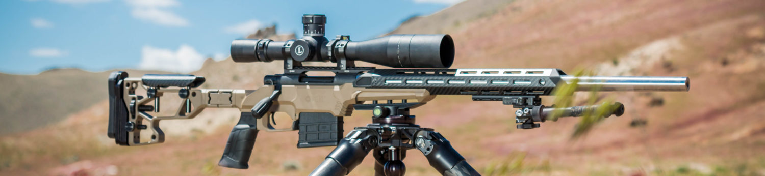
My friend is an exceptional painter (before he was in LE, he painted high end cars), so his skill set is impressive. KG Gunkote was used on the metal and Duracoat on the stock. When he finished the rifle, this is how it looked!


The post will be updated once he shoots it.
UPDATE April 21, 2015: It shoots!
My friend mounted a Nightforce scope and loaded up some 120 grain Sierra MatchKings over Varget. He didn’t bring a chronograph, so no velocity data yet.

5 shots, including cold bore, 100 yards, .548″(.523 MOA).

3 shots at 100 yards, .373″ (.356 MOA).

3 shots, 100 yards, .384″ (.367 MOA).
UPDATE April 27, 2015:

He did some more load development with 3-shot groups and the 120 SMK. This was at 100 yards, .249″ (.238 MOA). He is going to load up some more ammo and get some five shot groups. He will also get some velocity data on the next trip.
Like this post? Subscribe to Rifleshooter.com on the top right hand corner of this page and never miss a post!
Need parts to build a custom Remington 700? Check out Brownells!


You must be logged in to post a comment.