Remington 700 Rebuild: Transforming a Factory 700 AAC Rifle to a Custom Precision Rifle

Taking a factory Remington 700 and turning it into a custom rifle

Customized Remington 700 chambered in 243 Winchester. The AICS-AX 2.0 chassis system provides a rock solid base for this gun.

Building a custom rifle allows the shooter to end up exactly with what he wants.  Any barrel length, any cartridge, any contour, you name it… you are only limited by your imagination.  Many custom rifles start out life as factory guns.  Here is how we converted our Remington 700 AAC -SD  (Advanced Armament Corporation) into a one of a kind, custom precision rifle.

The out of the box accuracy demonstrated by the Remington 700 Tactical 308 AAC-SD we tested was excellent.  The entry level tactical rifle performed flawlessly and exhibited sub minute of angle (MOA) accuracy.  The 20″ threaded barrel provided a quick handling package capable of delivering accurate shots under a variety of conditions. A full review can be found here.

Remington 700 AAC 308
Remington 700 AAC 308 donor rifle

Our proven Remington 700 Tactical 308 AAC-SD provided the action for our custom build.  Without getting into a lengthy discussion about the pros and cons of specific actions, possibly the biggest advantage to the Remington 700 is the wide range of aftermarket parts available for it.  In many ways, this is the AR15 or 10/22 of the bolt action rifle world.

In this article, our rifle will be transformed into a custom 243 Winchester precision rig that combines light recoil, with excellent external ballistics and commonly available brass.

We ordered the following items from Brownells for this article:

The contents of Rifleshooter.com are produced for informational purposes only and should only be performed by competent gunsmiths. Rifleshooter.com and its authors do not assume any responsibility, directly or indirectly, for the safety of the readers attempting to follow any instructions or perform any of the tasks shown, or the use or misuse of any information contained herein on this website.

All lathe work was conducted on a Grizzly 4003G lathe.

A few notes on the donor action used in this article:

  1. an over sized bolt knob was installed, see “Tactical bolt knob installation
  2. the bolt had been helically fluted by Kampfeld Custom
With the rifle on safe and pointed in a safe direction, we open the bolt to verify it is safe and empty.
With the rifle on safe and pointed in a safe direction, we opened the bolt to verify it was safe and empty.
Our Remington 700 AAC is removed from the stock.
Our Remington 700 AAC was removed from the stock.
The receiver is held in a vise with bronze pads.  A pin punch is used to drift the rear trigger pin which also removes the bolt stop and bolt stop spring.  Caution: be careful when removing the punch, the sear spring is now loose and must be caught or you can lose it.   The front trigger pin is then drifted, which allows the trigger guard to be removed.
The receiver was held in a vise with bronze pads. A pin punch was used to drift the rear trigger pin which also removes the bolt stop and bolt stop spring. Caution: be careful when removing the punch, the sear spring is now loose and must be caught or you can lose it. The front trigger pin was then drifted, which allowed the trigger to be removed.
The action is secured in a Brownells action wrench.
The action was secured in a Brownells action wrench.
The barrel is secured in a Brownells barrel vise with aluminum shims.
The barrel was secured in a Brownells barrel vise with aluminum shims.
Here is a side view of the set up.  The barrel vise with aluminum inserts (left) secures the barrel so the action can be unscrewed with the action wrench (right).
Here is a side view of the set up. The barrel vise with aluminum inserts (left) secures the barrel so the action can be unscrewed with the action wrench (right).
This barrel required a lot of torque to remove.  A cheater pope was used in conjunction with an allen wrench to tighter the barrel vise.  The cheater pipe was then attached to the action wrench to provide enough leverage to unscrew the action.
This barrel required a lot of torque to remove. A cheater pipe was used in conjunction with an Allen wrench to tighten the barrel vise. The cheater pipe was then attached to the action wrench to provide enough leverage to unscrew the action.
Here is why remove was so difficult, the barrel threads were coated in thread locker!
Here is why removal was so difficult, the barrel threads were coated in thread locker!

With the action removed, we can begin!  The first step was to true, or blueprint the action.  This process involved squaring the surfaces of the action and can be accomplished in a number of different ways.  We used a Manson kit, which has provided us excellent results in the past.

The surfaces of our action were trued to the bolt hole in the center of the receiver.  We performed the following operations:

  • cut the minor diameter of the receiver threads
  • cut the front surfaces of the receiver lugs
  • cut the receiver threads
  • cut the receiver ring (front surfaces of the receiver)
  • cut the front and rear faces of the bolt lugs
  • cut the bolt nose
  • lapped the rear faces of the bolt lugs
  • cut the bolt face

Performing these steps provided us a trued receiver ready to accept our barrel.

The action wrench is secured in a vise and the action is held in the wrench.
The action wrench was secured in a vise and the action was held in the wrench.
To true the action, we will use the excellent Manson kit consisting of a tap (top), reamer (bottom) and two tapered (..700-.705") bushings (bottom).
To true the action, we used the excellent Manson kit consisting of a tap (top), reamer (bottom) and two tapered (..700-.705″) bushings (bottom).
With the tapered bushings inserted into the bolt hole, the tap recuts the minor diameter of the receiver threads and squares the front edges of the receiver lugs.
With the tapered bushings inserted into the bolt hole, the tap re-cut the minor diameter of the receiver threads and squared the front edges of the receiver lugs.
The tap is then used to recut the receiver threads.
The tap was then used to re-cut the receiver threads.
The receiver tap serves as a guide for the receiver ring facing tool.  This tool has three carbide cutters that cut the front of the receiver ring square to the bolt hole.
The receiver tap served as a guide for the receiver ring facing tool. This tool has three carbide cutters that cut the front of the receiver ring square to the bolt hole.
The bolt is secured in a LaBounty fixture in the lathe.
The bolt was secured in a La Bounty fixture in the lathe.
A 35 degree high-speed steel profile tool is used to square the rear of the bolt faces.
A 35 degree high-speed steel profile tool was used to square the rear of the bolt faces.
Mostly for cosmetic reasons, we will also clean up the front edges of the bolt lugs and bolt nose.
Mostly for cosmetic reasons, we also cleaned up the front edges of the bolt lugs and bolt nose.
A very light pass with a right-hand high-speed steel turning tool and the front of the bolt looks much cleaner.
After a very light pass with a right-hand high-speed steel turning tool and the front of the bolt looks much cleaner (compare to photo above).
With the bolt removed from the lathe, it is time to inspect how the rear face of the bolt lugs fit against the front face of the receiver lugs.  Anti-seize is placed on both bolt lugs.
With the bolt removed from the lathe, it was time to inspect how the rear face of the bolt lugs fit against the front face of the receiver lugs. Anti-seize was placed on both bolt lugs.
The bolt is then placed in the receiver and closed with a slight rearward pressure.  Examining the bolt, we can tell the lugs are making good contact.
The bolt was then placed in the receiver and closed with a slight rearward pressure. Examining the bolt, we could see that the lugs were making good contact.
Since the bolt and receiver lugs fit so well together, lug lapping will be an easy task.  The rear of the bolt lugs are coated in Dykem and then a light layer of lapping compound.  The bolt is then inserted into the action and handle is moved up and down while gentle reward pressure is applied. After a few strokes the Dykem is gone indicating full contact between mating surfaces.
Since the bolt and receiver lugs fit so well together, lug lapping was an easy task. The rear of the bolt lugs were coated in Dykem and then a light layer of lapping compound. The bolt was then inserted into the action and the handle was moved up and down while we applied gentle reward pressure. After a few strokes, the Dykem was gone indicating full contact between mating surfaces.
The bolt face is trued using a specialized carbide cutter and the tooling block shown here.
The bolt face was trued using a specialized carbide cutter and the tooling block shown here.
Here is a look at the front of the cutter (right) and the front of the bolt face after the initial pass is made (left).  Notice the low spot in the center of the bolt face.
Here is a look at the front of the cutter (right) and the front of the bolt face after the initial pass was made (left). Notice the low spot in the center of the bolt face.

We like using Holland recoil lugs.   The over-sized .250″ thick double lug has tapered draft angles to allow its easy release in bedding applications and is ground to ensure both faces are parallel.  A pin was used to secure the lug in place.

Our rifle will be using a Holland recoil lug.  The holland lug is pinned in place.  This is done by securing the receiver in a special fixture and then drilling the pin hole on the milling machine.
We used a Holland recoil lug. The lug was pinned in place. This was done by securing the receiver in a special fixture and then drilling the pin hole on the milling machine.

The addition of an external bolt stop provides a nice custom touch.  In addition to being easier to access then the factory trigger guard mounted stop, the external bolt stop is far less likely to bind up in field conditions.

Our custom rifle will use an external bolt stop as well.  The slot for the bolt slot is cut on the milling machine using a 3/16" carbide end mill.
Our custom rifle uses an external bolt stop as well. The slot for the bolt slot was cut on the milling machine using a 3/16″ carbide end mill.
The external bolt stop requires a1/16" pin to secure it.  The receiver is oriented upright and a 1/16" solid carbide end mill is used to spot the hole which is then drilled through with a jobber length drill.
The external bolt stop required a1/16″ pin to secure it. The receiver was oriented upright and a 1/16″ solid carbide end mill was used to spot the hole which was then drilled through with a jobber length drill.

While the action is in pieces, it was a good time to polish the raceways to ensure smooth operation of the bolt.

Using a raceway lapping tools and some fine abrasive cloth, we smooth out the bolt raceways on the action.  The paper is lubricated with Do-Drill cutting oil and long even strokes are used.
Using a raceway lapping tools and some fine abrasive cloth, we smoothed out the bolt raceways on the action. The paper was lubricated with Do-Drill cutting oil and long even strokes were used.
Prior to working on the barrel, the barrel tenon length and bolt nose recess depth need to be calculated.
Prior to working on the barrel, the barrel tenon length and bolt nose recess depth needed to be calculated.

There are a number of ways to thread and chamber a rifle barrel and we have tried most of them.  We have found them all to work satisfactorily.  For this project we dialed in both ends of the barrel through the headstock.  Our tail stock  was painstakingly adjusted for second operations and our reamer was held in a Gre-Tan fixed (not floating) reamer holder.

A copy of the chambering worksheet that we used can be found here.

We used Viper’s Venom cutting oil as a lubricant with Brownells high-speed steel insert tools.  This combination of cutting tool and lubricant provides an excellent finish on stainless steel barrels.

Our Bartlein heavy varmint contour 6mm barrel blank is placed in our lathe.
Our Bartlein heavy varmint contour 6mm barrel blank was placed in our lathe.
A range rod is inserted into the barrel and the bore is indicated with a .001" dial indicator followed by a .0001" dial indicator.
A range rod was inserted into the barrel and the bore was indicated with a .001″ dial indicator followed by a .0001″ dial indicator.
The barrel tenon is cut to length and diameter.  The recoil lug should slide onto the tenon but not wiggle.
The barrel tenon was cut to length and diameter. The recoil lug should slide onto the tenon but not wiggle.
The tenon is coated in Dykem and then a series of cuts are made.  The intersection of the tenon and tenon shoulder is relieved to allow the recoil lug to sit tight against it, a relief cut is made .245" from the shoulder to end the threads and a chamfer is made at the chamber end of the barrel.
The tenon was coated in Dykem and then a series of cuts were made. The intersection of the tenon and tenon shoulder was relieved to allow the recoil lug to sit tightly against it, a relief cut was made .245″ from the shoulder (lug thickness less .005″) to end the threads and a chamfer was made at the chamber end of the barrel.
The lathe is adjusted for threading.  A 60 degree center gage is used to align the high-speed steel threading tool.
The lathe was adjusted for threading. A 60 degree center gauge was used to align the high-speed steel threading tool.
After a light pass, the pitch of the threads is checked.  In this case 16 threads per inch.
After a light pass, the pitch of the threads was checked. In this case, 16 threads per inch.
After a series of light passes, the threads are formed.
After a series of light passes, the threads were formed.
The action (without the bolt) and recoil lug are screwed onto the barrel.  The lug should fit tightly, without any play.
The action (without the bolt) and recoil lug were screwed onto the barrel. The lug should fit tightly, without any play.
The bolt nose recess is cut using a .705" piloted counter bore.  The depth of cut is determined using the dial indicator located on the lathe tailstock.
The bolt nose recess was cut using a .705″ piloted counter bore. The depth of cut was determined using the dial indicator located on the lathe tail stock.
To cut the chamber, a Fre-Tan reamer holder is used.  The reamer we be fed slowly with plenty of Viper's venom cutting oil.
To cut the chamber, a Gre-Tan reamer holder was used. The reamer was fed slowly with plenty of Viper’s venom cutting oil.

The chamber was cut in very light passes.  To do this, the reamer was coated in Viper’s Venom and inserted into the chamber.  The lathe was run at 70 RPM (our lathe’s slowest setting) and the reamer was slowly fed.  The lathe was then stopped and the reamer retracted and cleaned.  The process was repeated until the reamer reached full depth.

Our reamer is equipped with a Kiff-Lambeth adjustable reamer stop.  The stop allows for adjustments in depth of cut to be made in .001" increments. Here, the stop reaching maximum depth from our initial setting.
Our reamer is equipped with a Kiff-Lambeth adjustable reamer stop. The stop allows for adjustments in depth of cut to be made in .001″ increments. Here, the stop reaching maximum depth from our initial setting.

The reamer stop makes cutting a chamber to the correct head space easy.  The initial adjustment was made by eye.  A “go” gauge was held up next to the reamer and stop, and the stop was adjusted to cut too shallow.  After the initial cut, the reaming depth of cut determined by feeler gauges was halved, and that value adjusted into the reamer stop.  This process is repeated until the chamber is cut to depth.  There is no sense in rushing here.  If the chamber is cut too deep, the  shoulder must be reset.

The action, bolt, and lug are screwed onto the tenon with the "go" gauge in place.  A feeler gauge is used to determine how much deeper the chamber needs to be cut.
The action, bolt, and lug were screwed onto the tenon with the “go” gauge in place. A feeler gauge was used to determine how much deeper the chamber needed to be cut.
Once the action closes on the "go" gauge, the chamber is deep enough.
Once the action closes on the “go” gauge, the chamber is deep enough.
The bolt should not close on the "no go" gauge as shown here.
The bolt should not close on the “no go” gauge as shown here.

Since we planned on shooting long, high ballistic coefficient bullets, we made up a dummy cartridge.  Our cartridge  is 2.880″ long.  The inside of the AICS-AX magazines used by the AX chassis system are 2.900″ long.  Subtracting .020″ to allow the cartridge to feed gave us the 2.880″ length.

Since out reamer is cut to SAMMI specifications, the throat was not long enough to accommodate the round.  The throat needed to be lengthened.  To determine how much the throat needed to be extended, the existing throat can either be measured with a Hornandy overall length gauge, or as shown here, by measuring the protrusion from the rear of the barrel.

The AICS short action magazine generally allow round to be loaded to an OAL of 2.880".  This allows a .020" space for the round from front to back.
The AICS short action magazine generally allows round to be loaded to an OAL of 2.880″. This allows a .020″ space for the round from front to back.
Here is our magazine length dummy round and a new piece of Lapua brass.
Here is our magazine-length dummy round and a new piece of Lapua brass.
The case without the bullet protrudes from the chamber the same distance as the "go" gauge.
The case without the bullet protruded from the chamber the same distance as the “go” gauge.
The magazine length cartridge does not.  In order to maximize performance, the rifle will need to be throated.
The magazine length cartridge did not. In order to maximize performance, the rifle needed to be throated.
A 6mm throated is run in the chamber to lengthen the throat.
A 6mm reamer was run in the chamber to lengthen the throat.
With the longer throat, the magazine length dummy cartridge now fits.
With the longer throat, the magazine-length dummy cartridge fit.

With the chamber work complete, it was time to focus on the muzzle.  Our rifle was to be equipped with an OPS R3E2C muzzle brake as well as a thread protector for the applications where we wouldn’t want to use the brake.

The action barreled action is screwed back together so that the top of the barrel can be determined.  This is critical since the OPS brake, like many others needs to be timed and aligned a certain way.
The action and barrel were screwed back together so that the top of the barrel could be determined. This is critical since the OPS brake, like any directional brake, needed to be timed and aligned a certain way.
The barrel is then reversed in the head stock of the lathe.  A range rod is used to dial in the bore.
The barrel was reversed in the head stock of the lathe. A range rod was used to dial in the bore.
The muzzle is squared and a tenon for the brake, .600" long is turned.
The muzzle was squared and a tenon for the brake, .600″ long was turned.
The tenon is threaded for the brake.  In this case 24 threads per inch.
The tenon was threaded for the brake. In this case 24 threads per inch.

This brake, like many other directional brakes on the market, needed to be timed.  This means there is a top and bottom. On preexisting builds this is typically accomplished with the use of shim washers.  On new construction, the preferred method is to time the brake on the barrel.

To time the brake, the brake was installed after the tenon was threaded and cut.  The orientation of the top of the brake and top of the barrel were noted.  The tenon’s shoulder was then incrementally reset until they aligned.

To determine how much the shoulder needed to be set back, 1 was divided by the number of threads per inch.  In our case, 1/24=.042″.  This means for every .042″ the shoulder is set back, the brake will turn one revolution.  To make a half turn, divide this value in half, for a quarter turn by four and so on.  So if the brake needed to be turned one half revolution, (.042″)(.5)=.021″.  A .021″ cut allowed the brake to rotate one half a turn.

In practice, we made lighter cuts then needed to avoid taking off too much material.  If the shoulder is set back too far, the shoulder needs to be set back for nearly one full revolution.

The brake is screwed into place.  Note the outside diameter of the barrel and the brake match.  This was by design.  The shoulder of the tenon was located at the precise point that the diameters matched.  If you plan on turning down a brake, make sure you can- in the past we attempted to turn down a similar brake and it fell apart because the cuts were too deep.
The brake was screwed into place. Note the outside diameter of the barrel and the brake match. This was by design. The shoulder of the tenon was located at the precise point that the diameters matched. If you plan on turning down a brake, make sure you can- in the past we attempted to turn down a similar brake and it fell apart because the cuts were too deep.
to make a thread protector we start with a scrap piece of stainless steel.  This is a cut off from a barrel blank that was drilled and tapped 5/8-24.
To make a thread protector we started with a scrap piece of stainless steel. This was a cut-off from a barrel blank that was drilled and tapped 5/8-24.
Side view of the blank.
After turning down the outside diameter of the thread protector, the area is sanded with some abrasive cloth.  Perfect match.
After turning down the outside diameter of the thread protector, the area was sanded with some abrasive cloth. Perfect match.
A recess was cut in the threaded part of the muzzle and a slight taper cut into the thread protector.

Final assembly in the AX chassis is conducted once the rifle was coated in Cerakote.  To see how we applied Cerakote, check out our article here.  The AX chassis, is an updated version of the very popular AICS chassis system from Accuracy International.

AX chassis system
AX chassis system

Check out these specs from Brownells:

The AX AICS (Accuracy International Chassis System) brings the ergonomic and functional benefits of the advanced Accuracy International AX sniper rifle system to the Remington 700 platform. A far superior chassis system suitable for any environment and mission, the AX AICS provides a degree of modularity and configurability that cannot be achieved with a traditional stock. Quick and easy to install, requiring no specialized gunsmithing, the AX AICS is available for short and long Remington 700 actions in .308 Win, .300 Win Mag and .338 Lapua Magnum families of cartridges. Built from polymer and alloy, the AX chassis is more than just a stock!

  • Full length aluminum chassis. The stiffness chassis gives the rifle a rugged, environmentally stable platform to enhance accuracy and zero retention. The action is attached to the chassis by two bolts (supplied) and retained in a self-aligning vee block bedding system which eliminates the need for bedding.
  • Folding chassis. When folded, the overall length is reduced by 8”. Ideal for rapid deployment from a vehicle, the stock locks in the folded position to avoid noise. Release by simply pulling the butt, the wear compensated hinge ensures total rigidity in the extended position.
  • Pistol grip.
  • Adjustable cheekpiece. The standard adjustable cheekpiece adjusts left/right as well as for height to obtain optimum cheek position when using night vision equipment or telescopic sights with large objective lenses.
  • Butt pad. Chassis systems are fitted with a bolt-on soft rubber pad with 10 & 20mm spacers as standard.
  • Bipod adapter. The chassis has a fixing point for Harris Bipods fitted as standard.
  • Magazine. Surface toughened and finished with a multi-part, anti-corrosion, low friction coating. One 5 round magazine is supplied as standard. The chassis design makes loading faster and more positive – no need to lift the rifle.
  • Forend mount assembly. 16” long action or 13” short action free float tube forend featuring a keyhole slot system for quick and securely attaching modular rail sections for mounting accessories. One 80mm rail and one sling loop included as standard.

In the past we have had excellent luck with the AICS systems.  They eliminate a large amount of guess work building rifles.  Unlike fiberglass stocks which require a little bit of skill to properly install, the AICS goes on easy and is hard to screw up. Since we are using a Jewel trigger, we needed to open up the inside of the chassis to allow it to function properly.

The Jewel trigger's safety protrudes further from the right side and front edge of the trigger assembly then the factory trigger.  Because of this, we need to open up the trigger area in the stock more.
The Jewel trigger’s safety protrudes further from the right side and front edge of the trigger assembly then the factory trigger. Because of this, we needed to open up the trigger area in the stock more.
The action area of the AX chassis.  Note the area we relieved on the milling machine to allow the safety to properly function on the Jewel trigger.
The action area of the AX chassis. Note the area we relieved on the milling machine to allow the safety to properly function on the Jewel trigger.
The front, then rear action screws are torqued to specification.
The front, then rear action screws were torqued to specification.
Then the forearm is attached with 10 screws.
Then the forearm was attached with 10 screws.
Finally, the olive drab covers are reinstalled.
Finally, the olive drab covers were installed.
A Badger rail, Nightforce F1 3.5-15 scope and Spuhr mount complete the package.
A Badger rail, Nightforce F1 3.5-15 scope and Spuhr mount completed the package.
Customized Remington 700 chambered in 243 Winchester.


Initial evaluation

With the rifle fully assembled, we headed to the range with three different loads using Sierra 107 grain MatchKing in Lapua brass over Reloader 22 powder and Tula large rifle primers.

For load development, we fired multiple three round groups from 100 yards.  The rifle was shot off a bench from a bipod with a rear bag. Results are found below:

Load # Velocity (FPS)/sd Average Accuracy Best Group @100yds
1 2885 sd 5 .650” .464”
2 2952 sd 15 .659” .543”
3 2996 sd 21 .511” .301”


This is our best 3 shot load development group at 100 yards, .301".  We are quite happy with it.
This is our best 3 shot load development group at 100 yards, .301″. We are quite happy with it.

Heading to a larger facility, we found the combination of light recoil, flat trajectory and accuracy allowed us to easily make hits in excess of 600 yards (the longest range available).  We did fire one, five shot group at 300 yards which measured 1.882″.

5 round 300 yard group measuring 1.881".
5 round 300 yard group measuring 1.882″.
A view of the our rifle on the firing line.  The front rifle is the 308 we were testing.
A view of the our rifle on the firing line. The rear rifle is the custom 243 prior to being finished with Cerakote.

We are pleased with the finished package.  Our light recoiling rifle is capable of sub 1/2 MOA accuracy without extensive load development on the first run.  We will report back when we get some more load development completed.
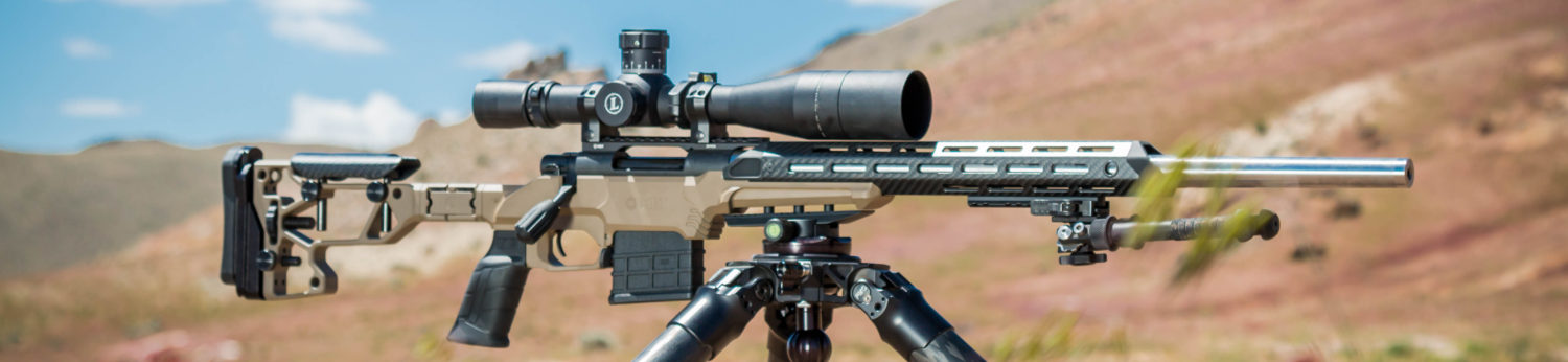
Before:

Remington 700 AAC 308

After:

Even the Golden Retriever thinks its cool!
Customized Remington 700
A Badger rail, Nightforce F1 3.5-15 scope and Spuhr mount complete the package.
Customized Remington 700 precision rifle

To customize your Remington 700, or for any other gunsmithing supplies, make sure you visit Brownells.