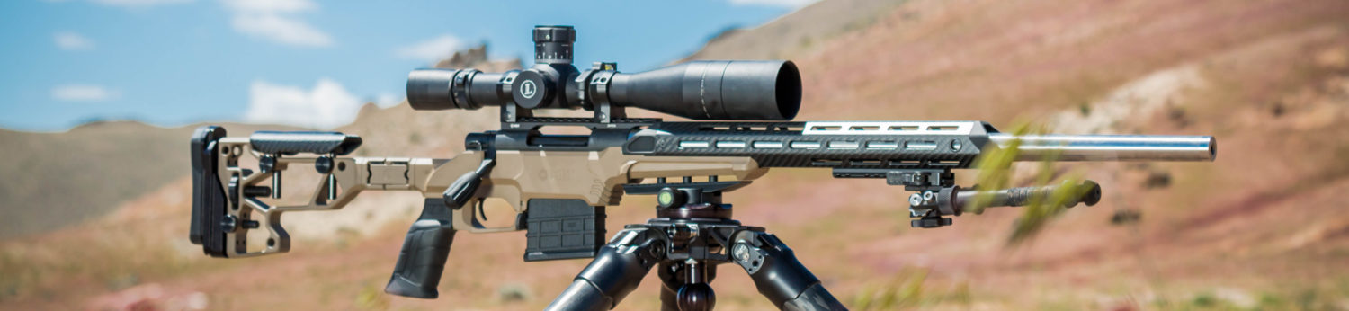
Building a Custom Remington 700 .308 Tactical Rifle
Who doesn’t love a heavy barrel .308?
Our receiver for this project is a Remington 700 short action that had been coated by Fail-Zero with their EXO Nickel Boron coating. Previously used to evaluate the TAC21 chassis system, we decided to build a heavy barreled .308 rifle with it.
We elected to head in the direction of an M40ish build- meaning we like heavy barrels, flush cups, UNS mounts and olive drab stocks. Tactical rifle, precision rifle, pick a name…The idea of this project it to end up with a rifle that we could use for a number of tasks, from local tactical rifle matches, mid range F-class (no muzzle brake), unknown distance shooting and to employ at various training programs. While you can certainly build a specialized rifle for each one of these disciplines, we wanted something with a little more versatility. Why 308, and not 260 or 243? We wanted the the ability to use off the shelf match ammunition.
We elected to equip our rifle with a 24″ #7 Shilen select heavy barrel, McMillian A5 stock and Surgeon bottom metal. The #7 profile is heavy, but not obscenely so. Balanced with the McMillian A5 stock and a quality optic, the rifle has mild recoil and will not punish the user.
Building a bolt action rifle requires quite a few steps. We decided to break this down into blueprinting the action, lapping the bolt lugs and truing the bolt face, threading and chambering the barrel, crowning the barrel, finishing the rifle and reassembly. For the sake of this article, we will be primarily focused on the more skilled steps in the process, so the initial disassembly and final reassembly are not covered in detail. Both of these topics are covered elsewhere on this site.
We ordered the following parts and supplies from Brownells:
The contents of Rifleshooter.com are produced for informational purposes only and should be performed by competent gunsmiths only. Rifleshooter.com and its authors, do not assume any responsibility, directly or indirectly for the safety of the readers attempting to follow any instructions or perform any of the tasks shown, or the use or misuse of any information contained herein, on this website.
Blueprinting the action
In order to blueprint the action, the trigger assembly, bolt stop, ejector and firing pin assemblies need to be removed. The steps required to accomplish these tasks are shown here. Once the parts are removed, the action can be trued, or blueprinted.
Our Remington 700 short action. It looks like stainless, but it’s not. Its is a blued receiver that has been coated by Fail Zero in their EXO proprietary Nickel Boron coating.We will start by blueprinting, or squaring our action. The Manson kit makes this simple.The Manson action blueprinting kit utilizes two tapered bushings inside the action to guide the receiver reamer and tap.The action is secured in an action wrench. The wrench is held in a bench vise.We run the receiver reamer, lubricated with Do-Drill, into the action to clean the minor diameter of the threads and square the receiver lugs.The receiver tap is used next. Coated with Do-Drill, this cleans up the major diameter of the threads and provides a bearing surface to true the front face of the receiver.This receiver ring tool has a bronze bushing that is guided by the receiver tap to square the front face of the receiver.The tool only requires light pressure to cut. The three carbide blades, lubricated with Do-Drill, are sharp and make short work of the required cuts.A few turns of the receiver ring tool are made and we check the results. The shiny spots indicate areas that are freshly cut. A few more turns are needed.The front of the receiver is now square.A spring loaded block is used to lap the bolt lugs true.Lapping compound is carefully applied to the front edge of the receiver lugs.Layout fluid is applied to the back edges of the bolt lugs to indicate progress.The tool bolt is inserted into its closed position and the spring loaded bolt lapping tool is screwed into the front of the receiver.The bolt handle is then lifted….
and closed repeatedly.When approximately 90% of the bearing surfaces are true, lapping is complete and the bolt and action are thoroughly cleaned to remove any remaining lapping compound.The bolt face is trued using a specialized carbide cutter and the tooling block shown here.Layout fluid is applied to the bolt face to indicate when the surface is flat.A drop of cutting fluid is placed on the bolt face and the tool is inserted underneath the extractor.The bolt and tool are inserted into the receiver. The tooling block guides the carbide cutter. A small wooden wedge is used to pull the bolt lugs tight against the receiver lugs while the cut is made.
A drill is used at low rpm to make the cut. It is critical to go slow and check firing pin protrusion when complete.Here is the trued bolt face, ready to go.
Threading, chambering and crowning the barrel
With the blueprinting complete, a depth micrometer and action worksheet are used to calculate the barrel tenon, head space, and bolt nose recess measurements.We always take our time and triple check all measurements.This is the blank we will be using. It is a Shilen select, #7 contour, 1:10 twist 30 caliber. We need to cut at least an inch off the chamber end, per manufacturers instructions.The barrel is mounted in a spider on the head stock of the lathe. We dial indicate off the outside surface of the barrel and square the face prior to proceeding. NOTE: we left the barrel protruding longer then necessary from the front edge of the spider in order to photograph the process. Normally, the barrel would not protrude this far.The other end of our head stock has a four screw spider to center the other end of the barrel.
A range rod is used to dial in the bore. The opposite end of the rod is held in the tail stock chuck. The rod has different bushings in .0002″ intervals. We selected a bushing that has a “light drag” when inserted into the bore.This is the set up we use to dial in the bore. Note the plumb bob providing tension on the range rod. A .001″ dial indicator is used to center the bore inside the spider. The range rod is then backed out to the chamber end of the barrel and the outside spider is used to center it. Once the range rod indicates to within .001″, a .0001″ dial indicator is used and the process is repeated until the bore is dialed in to within .0001″. At the end of this article, links are provided to provide further information on how a bore is dialed in.The face of the barrel is squared and the barrel tenon is cut to the length we calculated on our worksheet. We like to use high speed steel insert tooling and Viper’s Venom cutting oil when working on stainless barrels.Our oversized, Holland recoil lug fits well on the tenon. Note the small space in between the recoil lug and front edge of the barrel tenon. This is present because the tool has a slight radius. A small plunge cut will eliminate this condition.We make a plunge cut .005″ less then the thickness of the lug from the tenon shoulder. This will allow the action to tighten up against the lug. Additionally, the lug will be on a smooth bearing surface, rather then sitting on threads.A 60 degree center gauge is used to align the high speed steel threading tool. The compound is set to 29.5 degrees and the lathe is set to cut 16 teeth per inch. The threads are then cut on the lathe.Here is our threaded tenon.The bolt nose recess is cut with a piloted counter-bore secured in a floating reamer holder.A dial indicator held in a magnetic mount is used to determine depth of cut. The spring clamp is attached to the tail stock quill.The finished bolt nose recess cut.The action is screwed into place and the bolt closed to verify the tenon, threads, and bolt nose recess are correctly cut.
A Manson .308 Match reamer is equipped with an adjustable reamer stop. The stop is set short of the “go” head space gauge.
The reamer is coated in Viper’s Venom cutting oil and slowly fed into the chamber end of the barrel. We cut .025″ at a time. Stop the lathe, retract the reamer, clean & lubricate it and reinsert it a few thousandths short of the previous cut and repeat the process. The chamber is cut until the reamer stop contacts the end of the barrel.
The go-gauge is held with the bolt’s extractor.
The go-gauge is inserted into the bolt face and the bolt is inserted into the receiver which has been threaded onto the barrel and is hand tightened. Then a feeler gauge is used to measure any space between the receiver and the recoil lug. If space is found the chamber depth needs to be increased by that same amount. Don’t take all that material in one pass. Cut that dimension in half and repeat the process until it closes on the go-gauge with the receiver tightened against the recoil lug without any gap present.The dial on the reamer stop is turned back to half of the depth recorded on the feeler gauges and the chamber cut to depth. The chamber is then measured using a go-gauge and feeler gauge. Once the go-gauge falls the chamber is cut to depth.The no-go gauge is inserted into the chamber. The handle should not close. If it does, the shoulder needs to be reset to correct this condition.
Crowning the muzzle
We decided on a finish length of 24″. The barrel is measured and saw cut.To work on the crown the muzzle is inserted into the spider.The bore is dialed in using a ground rod with bushing. The bore is dialed in with a .001″ dial indicator, followed by a .0001″ indicator.A boring bar equipped with a high speed steel insert is used to cut the crown.
The crown is flat around the bore, then chamfered 45 degrees until it reaches the end of the muzzle.The barrel is secured in a barrel vise and an action wrench attached to a torque wrench is used to secure the action to the barrel.
A stamping guide is attached to the barrel so the caliber, “308 WIN”, can be stamped into the barrel. The guide uses a series of shims to make sure the parts are evenly advanced.
Here is the stamp on the barrel.
Finishing the rifle
Parts are attached to soft iron wire and degreased using TCE.
Rubber plugs are placed in both ends of the bore prior to sand blasting.
All parts are blasted with 100 grit aluminum oxide and cleaned with compressed air. The parts are then thoroughly rinsed with TCE to remove any remaining oils.
Graphite black Cerakote is applied to all metal parts. Parts are placed in a curing oven to harden the finish. When the parts are removed the rifle is reassembled.
Our rifle will be equipped with a Universal Night Sight mount. In this case a Badger embedded front rail (EFR). We had McMillian inlet the stock to receive the EFR.
The Badger EFR is glued into the stock with Marine Tex epoxy. Release agent is applied to all interior surfaces to prevent the epoxy from sticking to them.
A layer of Marine Tex epoxy is applied to the edges of the EFR inlet as well as all mating surfaces of the EFR. The EFR is then placed into the stock.
The rifle is assembled and the EFR’s alignment is checked to make sure it is straight. Cotton swabs and denatured alcohol are used to clean up excess epoxy. (Yes, the work area is a little messy)
Prior to heading to the range we completely reassemble the rifle and conduct a function check. Critically, we verify the trigger is safe and properly functioning and that head space is correct. The McMillian A5 stock supplied by Brownells had been inletted for Surgeon bottom metal by McMillian. For our test firing session we selected a Leupold Mark 4 4.5-14x50mm optic held in Badger Rings on a 20 MOA Badger base. Ammunition was Federal factory 168 grain Gold Medal Match Ammunition.
Uncasing our custom 308 rifle for its first trip to the range.Side view.
These are the initial groups we shot. After a single round to verify function, the rifle was bore sighted. A second round was shot at 50 yards and a dope change was made. At 100-yds, rounds 3, 4 and 5 (.509″) were then fired as a group, followed by rounds 6-10 (.688″). Temperature was approximately 95F with humidity was over 90%.
Test firing was conducted from the prone position on the mat shown in the photo above. The Harris Bi-pod was placed with the legs forward of the wooden curb shown, on the sand. A Triad tactical tapered rear rest was used. The trigger was set to break at 3.5 pounds.
For a new gun, with factory ammunition, we are fairly pleased with the results. Our first group at 100-yards with rounds 3, 4 and 5 measured .509″. Our second five-round group, with rounds 6-10 measured .688″. While we would like to see better results with this, we are happy so far considering the range conditions and brutal mirage that was obscuring vision. Average accuracy from this gun from our initial session was .645″, with the largest 5-round group measuring .739″. We plan on working up some hand loads and heading back to the range in the near future.
UPDATE 9/28/14- I’ve shot the rifle quite a bit and accuracy has improved. I’ve managed quite a few 1/4 MOA 5-shot groups at 200 yards. Below is a ten-shot group I shot at 100 yards from my pack, no bipod. Here is a post I did on a new brake installation, How to cut and crown a rifle barrel and install a brake
It shoot well with the new brake. 10-rounds at 100 yards from 2 magazine fired off my pack.
A special thank you to Brownells for supplying the following:
Rifleshooter.com has partnered with The “Camp-Site” Sport Shop for all its firearm transfer and shipping needs. Camp-Site is committed to advancing the shooting sports by educating sportsman and promoting the shooting sports. Check out their website or visit their Guns America online store for quality new and used pieces.
6×47 (6-6.5×47) Lapua Review 6mm (.243″) cartridges are popular among target shooters in various disciplines. Low recoil and excellent external ballistics offer shooters the ability to use a flat shooting cartridge without getting beat up on […]
MAGPUL is a well known shooting accessory company founded in 1999 by former United States Marine, Richard Fitzpatrick. The original products were called MAGPULs, rubber loops attached to the bottom of a standard GI magazine […]
A look at how rifle barrels speed up: Measuring the increase of muzzle velocity in new barrels Seasoned shooters and barrel makers will often tell you new rifle barrels speed up. Normally they say something […]


You must be logged in to post a comment.